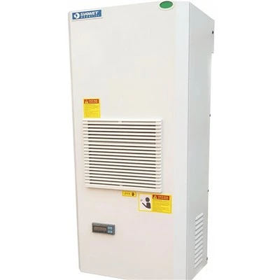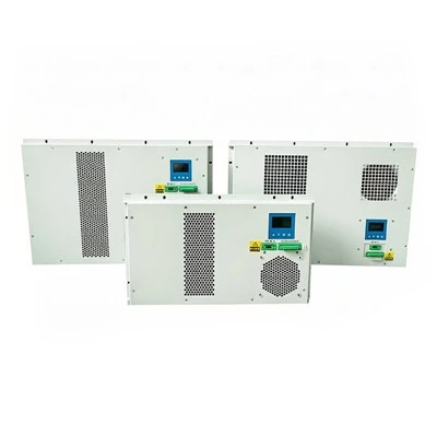


A complete system may include:
- Refrigeration unit (SAH series)
- Air duct
- Temperature control module
- Temperature sensor
- Signal output or alarm interface
- Power distribution and cable
- Mounting bracket and sealing gasket
Not every project needs all items. The system configuration depends on cabinet quantity, cabinet layout, total heat generation, and monitoring requirements.
Use the following table to decide the system type:
|
Condition |
System Type |
|
One cabinet, heat generation within one unit capacity |
Single-cabinet system |
|
Multiple cabinets in the same room, total heat generation within one unit capacity |
Multi-cabinet system with air duct |
|
Multiple cabinets far apart |
Distributed system with one unit per cabinet |
|
Cabinet heat generation higher than 3200 W |
Combine multiple units or use a larger cooling solution |
For multi-cabinet systems, cabinet spacing and air duct length affect cooling effect. If cabinet spacing is large, a distributed installation may be more suitable than a long air duct.
Air duct length affects air pressure and cooling capacity at the end of the duct. Before designing the duct, confirm:
- Distance between cabinets
- Height difference between cabinets
- Air duct route and bend quantity
- Air outlet position on each cabinet
- Return air path
If the air duct is too long or has many bends, air flow at the far end may be insufficient. In this case, increase the duct cross-section, reduce bends, or use a distributed system.
Temperature sensor placement affects temperature control accuracy. Recommended positions:
- Air return inlet of the cabinet
- Air outlet of the cabinet
- Near the highest heat generation component
- Upper part of the cabinet (heat accumulation area)
Do not place the sensor close to the air outlet, because it will read the cold air temperature instead of the cabinet internal temperature. Do not place the sensor on a heat source surface.
After installation, commission the system in the following order:
- Confirm all units are fixed and sealed
- Confirm air duct connections have no leakage
- Confirm temperature sensor wiring is correct
- Set the target cabinet internal temperature
- Start one unit and observe temperature change
- Start all units and record running current
- Check alarm and signal output
Record the following during commissioning:
- Cabinet internal temperature at each sensor
- Unit running current
- Air flow at each cabinet air outlet
- Ambient temperature
The temperature control module can be configured with signal output and alarm interfaces. Typical alarm conditions:
- Cabinet internal temperature above set point
- Unit running current abnormal
- Temperature sensor failure
- Power supply failure
For projects that need interlock with existing PLC or monitoring system, confirm the interface type and communication protocol at order confirmation. Batch orders can be customized.
Recommended maintenance schedule:
|
Interval |
Item |
|
Monthly |
Clean air inlet filter or fins, check temperature record |
|
Quarterly |
Check unit running current, check air duct connection |
|
Every 6 months |
Check temperature sensor accuracy, check sealing gasket |
|
Every 12 months |
Check refrigerant charge, check electrical connections |
Keep spare parts: air filter, sealing gasket, temperature sensor, fan.
Standard Configuration (SAH Series, Selected Models)
|
Parameter |
Unit |
SAH600 |
SAH1000 |
SAH1500 |
SAH2000 |
SAH2500 |
SAH3200 |
|
Cooling capacity |
W |
600 |
1000 |
1500 |
2000 |
2500 |
3200 |
|
Cabinet internal temperature range |
°C |
+25 to +38 |
+25 to +38 |
+25 to +38 |
+25 to +38 |
+25 to +38 |
+25 to +38 |
|
Cabinet external temperature range |
°C |
-5 to +55 |
-5 to +55 |
-5 to +55 |
-5 to +55 |
-5 to +55 |
-5 to +55 |
|
System pressure hold |
bar |
26 |
26 |
26 |
26 |
26 |
26 |
|
Power supply |
V/ph/Hz |
220/1/50 |
220/1/50 |
220/1/50 |
220/1/50 |
220/1/50 |
220/1/50 |
|
Input power |
W |
287 |
300 |
330 |
340 |
420 |
450 |
|
Cabinet internal air flow |
m³/h |
120 |
120 |
150 |
150 |
230 |
230 |
|
Cabinet external air flow |
m³/h |
180 |
180 |
230 |
230 |
290 |
290 |
|
Refrigerant |
- |
R22/R134A |
Same |
Same |
Same |
Same |
Same |
|
Protection level (internal/external) |
IP |
IP54/IP54 |
IP54/IP54 |
IP54/IP54 |
IP54/IP54 |
IP54/IP54 |
IP55/IP55 |
Q: How to decide between a centralized system and a distributed system?
A: Consider cabinet quantity, cabinet spacing, total heat generation, and air duct route. If cabinets are close to each other and total heat generation is within one unit capacity, a centralized system with air duct can be used. If cabinets are far apart or each cabinet has high heat generation, a distributed system with one unit per cabinet is more suitable.
Q: What should be recorded during system commissioning?
A: Record cabinet internal temperature at each sensor, unit running current, air flow at each cabinet air outlet, and ambient temperature. Compare the recorded data with the design target. If the cabinet internal temperature cannot reach the set point, check heat generation, air duct leakage, sensor placement, and unit capacity.
Hot Tags: electrical cabinet cooling system, China electrical cabinet cooling system manufacturers, suppliers, factory, cabinet air conditioner pressure switch, cnc cabinet air conditioner, control enclosure air conditioner, Dc Cabinet Air Conditioner, enclosure air conditioning unit, network cabinet air conditioner